Hardware
A Ø48 mm, four-layer board behind a 2.1″ round glass, in a standard 52 mm gauge body.
The unit
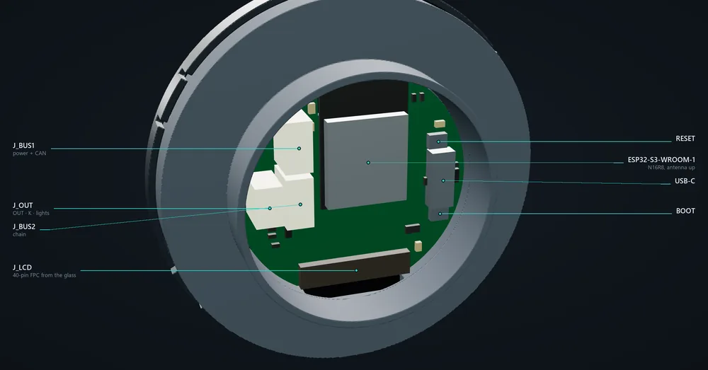
The glass and bezel sit on the dash; the body goes through the hole and everything plugs into the rear cap. USB-C on the back is for flashing and the console, with pin holes for BOOT and RESET.
The housing prints in PETG or ASA, so it copes with a hot dashboard. A touch version of the glass gets its own pod with a snap-on full-face bezel.
Specifications
| Display | 2.1″ round IPS, 480 × 480, ST7701S, about 1000 nit, constant-current backlight with 250 Hz PWM dimming |
|---|---|
| Processor | ESP32-S3 (ESP32-S3-WROOM-1-N16R8): 16 MB flash, 8 MB octal PSRAM, Wi-Fi and Bluetooth LE |
| Graphics | LVGL 9, 50 Hz refresh |
| CAN | Classic CAN (TCAN1044V), 500 kbps by default, switchable 120 Ω termination. Not CAN FD |
| K-line | L9637D with the tester pull-up on board, rated over 50 kbaud |
| Output | DRV8876 half-bridge: high-side or low-side, 1.5 A limit, over-current, thermal and under-voltage protection |
| Dash lights input | 12 V, dimmed 12 V, or 58d PWM down to about 5 % duty |
| Power | 12 V with PTC, TVS and reverse protection; 5 V buck, runs from USB on the bench (the glass stays dark on USB alone) |
| Plugs | 2 × JST PA-4 (power and CAN, pass-through), 1 × JST PA-3 (output, K-line, dash lights), USB-C |
| Body | Ø51.8 mm through a standard 52 mm hole; Ø76.4 mm head; U-bracket |
The board
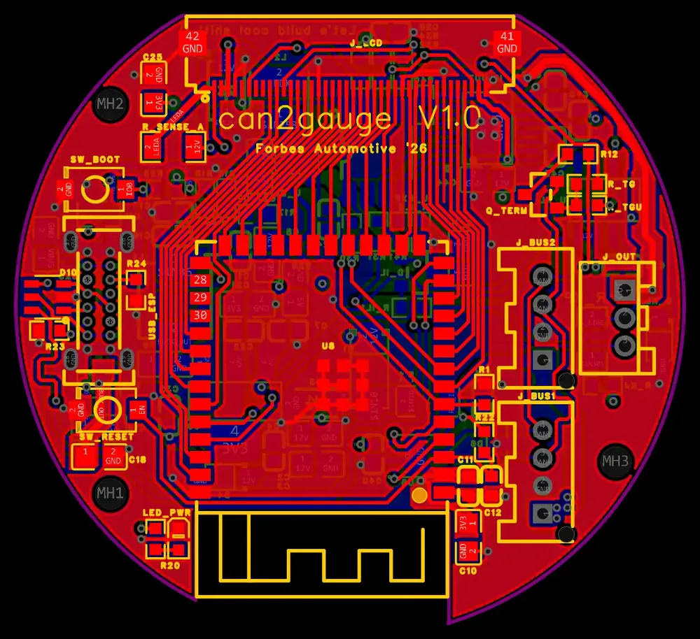
Four layers, with the ESP32-S3 module and the glass connector on the rear and the major chips on the glass side. There is no ADC on the board: analog sensors come in through the adc2can over CAN, which keeps the gauge small and the sensor wiring short.
Open source
The firmware, web UI, simulator and tools are on GitHub. Build it, change it, or send a fix.